Each installation has its own requirements: liquid source, flow, control method and operating conditions. Autolejek system components are selected for the particular application. This chapter explains the role of each device and helps you prepare the information needed to plan an installation. You can focus on the topics relevant to your system.
1
Dimensions and markings
Dimensions are the first topic for a reason. Without understanding standardised sizes, choosing the right materials can be difficult.
It is not only about buying the correct part, but also about avoiding a misleading offer. An unclear listing may indicate that the seller does not fully understand the product.
ISO 228-1 — how does a G thread designation relate to its actual dimensions?
ISO 228-1 describes parallel pipe threads identified by the letter G. The number in a designation such as G1 does not mean that the thread diameter is 1 inch (25.4 mm).
Where does the difference come from?
Pipe-thread designations are historical. The inch size originally referred approximately to the nominal inside diameter of a pipe, while the thread was cut on its outer surface.
G1 ≠ Ø25,4 mmThe actual outside diameter of a G1 thread is approximately Ø33.25 mm.
Common ISO 228-1 thread sizes
ISO 228-1 thread
Nominal size
Thread outside diameter
G1/8
1/8"
≈ 9,73 mm
G1/4
1/4"
≈ 13,16 mm
G3/8
3/8"
≈ 16,66 mm
G1/2
1/2"
≈ 20,96 mm
G3/4
3/4"
≈ 26,44 mm
G1
1"
≈ 33,25 mm
G1 1/4
1 1/4"
≈ 41,91 mm
G1 1/2
1 1/2"
≈ 47,80 mm
G2
2"
≈ 59,61 mm
Example — G1
A G1 thread according to ISO 228-1 has the following parameters:
outside diameter: ≈ 33,25 mm
number of threads per inch: 11 TPI
pitch: ≈ 2,309 mm
thread angle: 55°
type: parallel thread
Measuring the outside diameter of a male G1 thread with callipers will therefore give approximately 33 mm, not 25.4 mm.
What does DN mean?
DN is the designation for the nominal size of piping-system components defined by ISO 6708. It consists of the letters DN followed by a dimensionless whole number that is only indirectly related to an actual dimension in millimetres.
DN can be understood as a size class for a pipe and the components used with it, such as valves, water meters, flow meters, filters, or pumps.
Two pipes marked DN25 can have different actual inside diameters and still belong to the same nominal system-size class.
When documentation relates the nominal value specifically to an inside diameter, it may use DN/ID (Inside Diameter). DN/OD (Outside Diameter) is used when it relates to an outside diameter. DN by itself does not identify which actual dimension should be measured.
DN and NPS
NPS (Nominal Pipe Size) is the North American system of nominal pipe sizes, while DN is the international nominal-size system for piping components. Common correspondences are used in practice, for example DN25 ↔ NPS 1 and DN32 ↔ NPS 1 1/4. This is not a conversion from inches to millimetres or a definition of the pipe's actual diameter.
DN and the thread designation describe different properties of a component. Do not derive the connection size from DN alone—read both designations from the documentation for the specific device.
Practical example — DN20 and a G1 thread on the GSD8-R
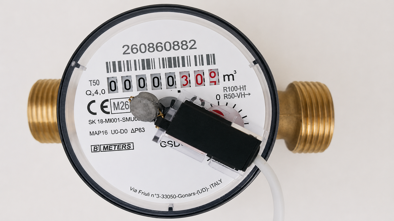
Below is an extract from the documentation for the BMETERS GSD8-R water meter. In the “Dimensions and weight” table, the manufacturer specifies 1″ in the “D Thread” row for the DN20 variant.
Illustration from manufacturer documentationExtract from the BMETERS GSD8-R product datasheet — dimensions and weight.Open the documentation →
DN20 identifies the meter's nominal size, while “D Thread = 1″” means a G1 connection thread made according to EN ISO 228-1. Here, D is the name of a dimension in the technical drawing; it does not state that the thread diameter is one inch.
DN20 / G1 / Ø≈33,25 mmMeasuring the thread's outside diameter on this meter with callipers gives approximately 33.25 mm. This agrees with the G1 thread dimension and again shows that DN20 and 1″ are not physical dimensions to be read directly as 20 mm or 25.4 mm.
How should the markings be read?
DN20 · G1 · Ø≈33.25 mmThese are three different pieces of information: DN20 identifies the meter's nominal size, G1 identifies its connection thread, and approximately 33.25 mm is that thread's actual outside diameter. None of these values should be treated as a direct conversion of the others.
Do not identify an unknown thread from its diameter alone. Also check its pitch, profile angle, parallel or taper form, and intended sealing method, then compare the results with the table for the relevant standard. G and R threads may have a similar diameter and the same pitch, but they are not the same thread type. Do not convert the inch designation directly using 1" = 25.4 mm.
2
Water meter / flow meter
Many devices can measure liquid flow and volume. They differ in construction, operating principle, and the way they communicate the result.
The result may be shown on a mechanical register, provided as electrical pulses, sent over a wired M-Bus connection, transmitted wirelessly via wM-Bus, or exposed through another interface. Autolejek uses a simple and common method: it counts electrical pulses.
This section is not intended to describe every type of water meter and flow meter. Its purpose is to explain the key characteristics needed to choose a device that suits a particular installation.
Water meter or flow meter?
A water meter is an instrument designed to measure the volume of water passing through it. It usually has a register showing total volume, while a pulse-output version can also send readings to a controller. Flow meter is a broader term: a device may measure instantaneous volumetric flow, total volume, mass flow, or several of these quantities. A water meter is therefore not the opposite of a flow meter; it is a water-specific measuring instrument that may use different measuring principles.
Common types of flow meter
The clearest way to distinguish these devices is by their measuring principle. The overview below is not exhaustive, but covers the types commonly encountered when measuring liquids.
Rotor and turbine metersThe liquid turns a rotor, and its speed is converted into flow rate. A Hall-effect sensor or another transducer may generate pulses for successive rotations. The SEA YF-G1 works this way. The design is simple and inexpensive, but its reading may be affected by viscosity, contamination, flow profile, and wear of moving parts.
Positive-displacement metersThe mechanism repeatedly isolates portions of liquid with a known volume and counts their passage. Common mechanisms include pistons, nutating discs, vanes, and oval gears. Oval-gear meters are well suited to viscous liquids such as oil, but contain moving parts and produce a pressure drop.
Electromagnetic metersThese meters sense the voltage produced as a conductive liquid moves through a magnetic field. They have no rotor or other components driven by the liquid, but require power and a sufficiently conductive medium. They are not a universal choice for oil or very poorly conductive liquids.
Ultrasonic metersThese determine flow from ultrasonic transit time or the Doppler effect. They may have no moving parts, and clamp-on versions are mounted outside the pipe. Accuracy nevertheless depends on correct installation, pipe material and dimensions, and conditions within the liquid.
Coriolis mass metersThese observe changes in the vibration of one or more tubes carrying the medium and measure mass flow directly. They often also measure density and temperature. They are highly versatile, but usually more expensive and complex than a simple dosing system requires.
For Autolejek, the measuring principle alone does not determine compatibility. The device must suit the liquid and flow range and provide a suitable pulse output. M-Bus, wM-Bus, a 4–20 mA analogue output, or a display alone does not replace a compatible pulse signal.
The device must suit the liquid
First determine what will be measured: cold or hot water, drinking water, oil, fuel, liquid fertiliser, or another liquid. Check permitted viscosity and temperature, chemical compatibility of the body, seals, and measuring components, required cleanliness, and maximum pressure. A device intended for water may measure oil inaccurately, seize, or be damaged even when its thread and flow range appear suitable.
Cold and hot water
Water meters are available in versions intended for cold or hot water. They differ in permissible operating temperature and in the materials used for internal components and seals. Do not select a meter solely by its body colour — check the temperature class and maximum medium temperature in its datasheet.
If the device will handle drinking or domestic water, also check the required approvals and whether its materials are certified for contact with that water.
Pulse output — the essential requirement
Autolejek requires a water meter or flow meter that generates at least 1 pulse for every 1 litre of measured liquid.
≥ 1 imp./lA device rated at 1 pulse per 10 litres has a 10-litre resolution and is unsuitable for accurate dosing with Autolejek — reject such an offer.
5 VA water meter or flow meter connected directly to Autolejek must be compatible with 5 V operation. Its pulse output must be suitable for a 5 V logic input, and the signal voltage must not exceed 5 V. For a passive contact such as a reed switch, verify that it can operate in a 5 V circuit.
The number of pulses determines reading resolution, but does not by itself guarantee measurement accuracy. Accuracy, repeatability, and flow range must be checked separately in the manufacturer's documentation.
Mechanical contact bounce
Mechanical pulse sensors, such as reed switches, may exhibit what is known as contact bounce. When their spring contacts close or open, they do not always settle into the new position immediately and cleanly. For a very short time, they bounce against each other, producing a series of rapid transitions between the open and closed states.
An electronic circuit may interpret each of these transitions as a separate pulse. As a result, one real sensor operation may be counted several times, causing the indicated volume to be higher than the actual volume.
Example voltage waveform at the output of a mechanical sensor. The dashed lines mark the period during which contact bounce may occur; after it ends, the signal settles.
Contact bounce is reduced with a technique known as contact debouncing or filtering. After detecting a pulse, a circuit may ignore further input transitions for a specified period, or it may require the signal to remain continuously active for a defined minimum time. Only then is the pulse accepted as valid.
Autolejek implements the second approach. After enabling filtering in the settings, the user specifies how long the signal must last before it is counted. The value is entered in microseconds (µs). Signals shorter than the configured time are rejected as potential interference or contact bounce. The threshold must be selected carefully: if it is too short, bounce may pass through; if it is too long, valid pulses may be rejected.
Understanding water meters using the BMETERS GSD8-R
Once the type of liquid is known, the next step is to determine the required flow rate. Using the BMETERS GSD8-R as an example, we will see how to read the key markings and how mounting position affects the minimum measurable flow.
The letter Q denotes volumetric flow rate: the volume of water passing through the meter in a given time.
Q4
Overload flow rateThe highest flow rate at which the meter can operate correctly for a short time. The meter is not intended to run continuously at this point.
Q3
Permanent flow rateThe highest flow rate at which the meter can operate continuously under rated operating conditions.
Q2
Transitional flow rateThe boundary between the lower and upper measuring ranges, which have different maximum permissible errors.
Q1
Minimum flow rateThe lowest flow rate at which the meter is required to remain within its maximum permissible error. Its value depends in part on the R ratio and mounting position.
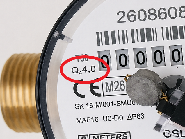
Q3 4.0 marking on the water-meter dial.
The Q3 4.0 marking means a permanent flow rate of 4.0 m³/h, or 4,000 L/h. The meter can operate continuously at this flow under rated conditions. For this GSD8-R variant, the datasheet specifies Q4 = 5 m³/h.
Not every manufacturer foregrounds the Q1–Q4 designations. The SEA YF-G1, for example, directly states a range of up to 100 L/min. Regardless of presentation, always check the datasheet for the exact device variant or ask the seller to provide it.
Next step — mounting position
Yes, mounting — more precisely, meter orientation — must be checked before calculating the minimum flow. The same meter can have a different R ratio (explained below), and therefore a different Q1, depending on the position of its body and dial.
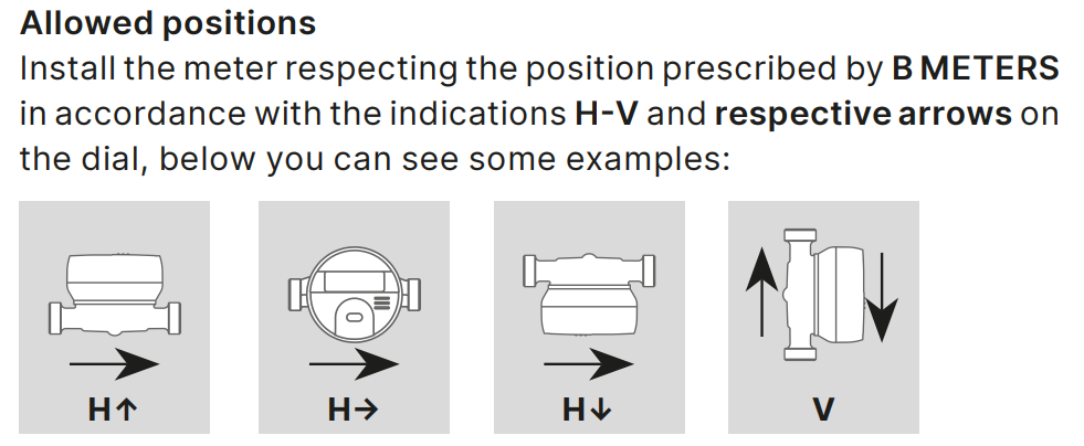
Illustration from manufacturer documentationExample mounting positions from the BMETERS instructions.Installation instructions →
The large arrow shows the direction of water flow. The smaller arrow describes the meter dial's position relative to vertical. H means installation in a horizontal orientation, while V means installation in a vertical orientation.
H↑horizontal orientation with the meter dial facing upwards,
H→horizontal orientation with the dial turned sideways by 90°,
H↓horizontal orientation with the dial facing downwards,
V↑vertical orientation with the water flowing upwards.
For an Autolejek installation, position V means upward flow only. Do not install the meter so that water flowing down under gravity drives the turbine or impeller. Flow should be forced by pressure — this topic will be covered in a later section.
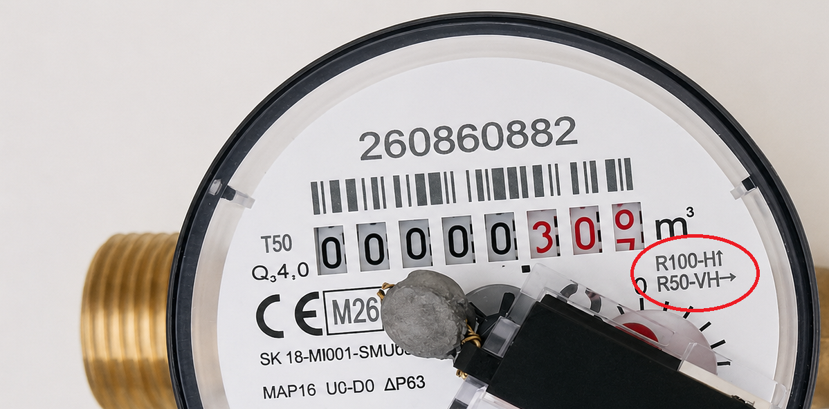
Position and R-ratio markings on the GSD8-R shown here.
The unit shown has two mounting-accuracy variants: R100 for H↑ and R50 for V↑ and H→. The general instructions also illustrate H↓, but this particular meter's dial does not list that position.
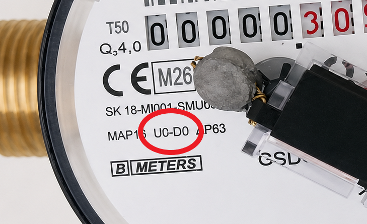
Observant readers may also have noticed the U0 and D0 markings on the dial — we will return to those later.
Minimum flow — calculating Q1
The R ratio is the permanent flow rate Q3 divided by the minimum flow rate Q1. Therefore:
R = Q3 / Q1thereforeQ1 = Q3 / R
Q1 for a GSD8-R with Q3 = 4.0 m³/h
Position
R
Calculation
Q1
H↑
100
4,0 / 100
0,04 m³/h = 40 l/h
V↑ / H→
50
4,0 / 50
0,08 m³/h = 80 l/h
Changing the position from H↑ to V↑ or H→ doubles the minimum flow Q1 from 40 to 80 L/h. The meter may still register flow below Q1, but the manufacturer no longer guarantees that it remains within the maximum permissible error.
Measurement error
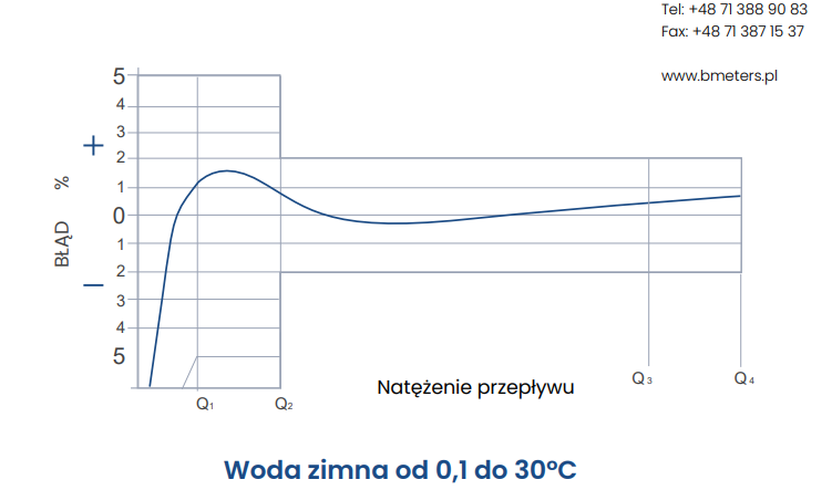
Illustration from manufacturer documentationExample error curve for a cold-water meter.View the BMETERS document →
The curve shows that error is not uniform across the range. A wider maximum permissible error applies between Q1 and Q2, while a narrower band applies from Q2 to Q4. Below Q1 the error can rise sharply, which is why correct mounting orientation and knowledge of the actual minimum flow are important.
Example — SEA YF-G1 flow sensor
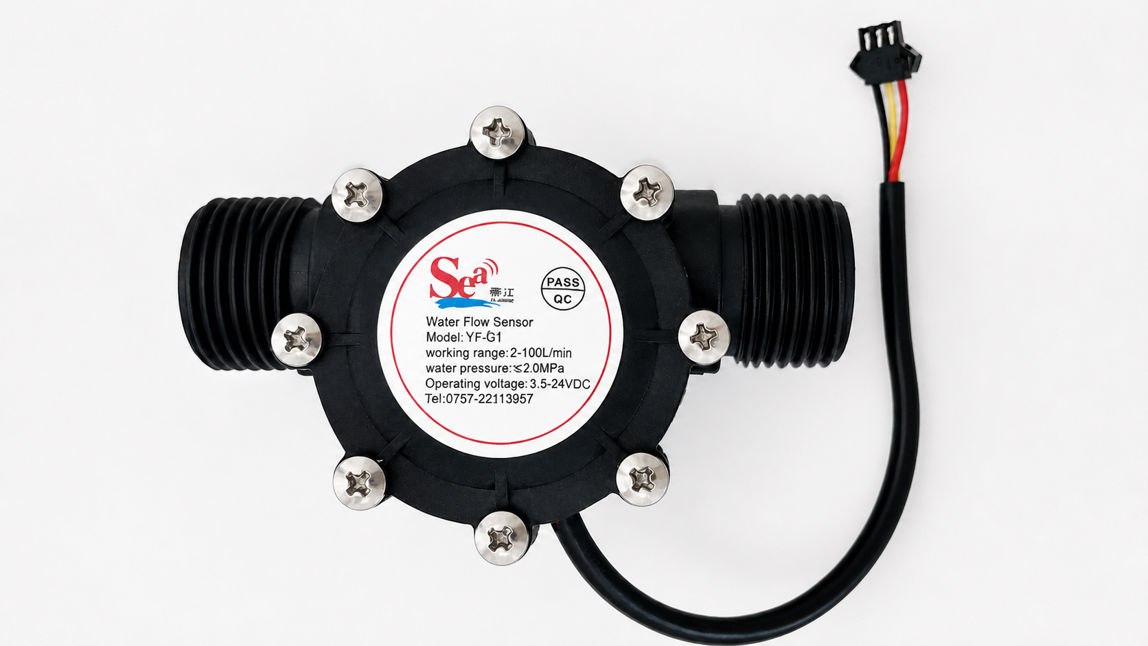
The SEA YF-G1 is a turbine water-flow sensor. It has G1 threaded connections and a DN25 nominal size.
SEA YF-G1 — an active three-wire water-flow sensor.
Key SEA YF-G1 datasheet parameters
Power supply
DC 5–24 V
Maximum operating current
15 mA (DC 5 V)
Flow range and stated accuracy
1–100 l/min, ±5%
Maximum liquid temperature
80°C
Maximum pressure
1,75 MPa
Signal duty cycle
50% ±10%
Pulse characteristic
f [Hz] = 1 × Q [l/min] ±3%
Nominal pulse count
≈ 60 imp./l
The formula means that at 30 L/min the nominal frequency is 30 Hz. In one minute the sensor generates 1,800 pulses for 30 litres, giving a nominal 60 pulses per litre. The YF-G1 therefore satisfies Autolejek's requirement of at least 1 pulse per litre.
The nominal 60 pulses per litre is only a starting value. The datasheet states ±5% measurement accuracy and separately gives a ±3% tolerance for the pulse characteristic. It is not clear whether these are independent errors, so they should not simply be added together. They do show, however, that entering a single datasheet coefficient cannot guarantee an accurate result for every unit across the full flow range.
Products sold as YF-G1 can be found with different stated characteristics, including approximately 60 or 64.8 pulses per litre. Do not copy a coefficient from a random listing — check the documentation for the exact variant and calibrate the unit you own.
Calibrate the sensor in its final installation:
pass an accurately measured volume of water through it and record the pulse count,
calculate the factor: pulse count ÷ litres,
repeat the measurement several times at low, typical, and high flow rates,
compare the results — if the factor changes noticeably with flow, one calibration constant will not provide high accuracy.
ConclusionThe SEA YF-G1 provides good pulse resolution, but its stated tolerances make precise calibration problematic. It is suitable where an error of several percent is acceptable; before using it for accurate dosing, test the individual sensor under actual operating conditions.
Use these questions to choose the right flow meter
Which liquid will be measured?Check viscosity, temperature, cleanliness, and material compatibility.
What will the flow rate be?Determine the minimum, typical, and maximum flow. All three should fall within the device's operating range.
Will it be cold or hot water?Choose the appropriate water-meter temperature class.
How many pulses are generated per litre?Autolejek requires at least 1 pulse per litre; more pulses provide finer dosing resolution.
How long can contact bounce last?For a mechanical output, check the maximum contact-bounce duration. It is needed to configure the Autolejek filter correctly. If it is not stated in the documentation, the seller or manufacturer should answer this question.
Does the device fit the installation?Check the thread, nominal size, pressure, flow direction, mounting position, and required straight-pipe length.
First match the device to the liquid and flow, then check the pulse output, and only then verify the connection dimensions. A matching thread alone does not mean that a flow meter is suitable for the installation.
Practical conclusionIn my experience, water meters such as the BMETERS GSD8-R are much more user-friendly for measuring water than flow sensors with a large stated error. A clearly specified metrological characteristic and a pulse rate of 1 L/pulse mean that troublesome individual calibration is unnecessary. You only need to configure the pulse rate correctly and install the device according to its documentation. The price difference is not particularly large either: a YF-G1 costs approximately PLN 70, while a GSD8-R costs around PLN 180.
Watch out for interferenceCounting pulses without flow requires diagnosis. Check the power supply, connections, cable routing and coil suppression. Route the pulse cable away from motors and power wiring. Select its type, length, shielding and route for the particular installation; 2 m is not a universal interference immunity limit. Filtering does not replace correct installation, and an excessive filter time can reject valid pulses.
3
Relays
A relay is an electrically controlled switch. A small current through its coil changes the position of contacts that can switch a separate circuit, such as a pump, solenoid valve, or combustion-engine kill wire.
This means the controller does not have to power the controlled device directly. It only commands a change of state, while the relay contacts open or close the appropriate circuit.
What is a relay made of?
A conventional electromagnetic relay contains three main working elements:
a coil that creates a magnetic field when energised,
a moving armature attracted by the magnetic field,
electrical contacts operated by the armature's movement.
What do COM, NC, and NO mean?
COM
common contactThe moving contact that connects alternately to NC or NO.
NC
normally closedConnected to COM while the coil is de-energised.
NO
normally openConnects to COM only after the coil is energised.
The DC circuit controls the coil, while the isolated contacts switch the AC circuit. With the coil de-energised, COM connects to NC and the NC lamp is on. Energising the coil moves COM to NO: the NC lamp turns off and the NO lamp turns on.
What happens during switching?
When the coil is de-energised, a spring holds the armature in its resting position. COM is then connected to NC, while the COM–NO circuit remains open.
Applying the correct voltage to the coil creates a magnetic field. It attracts the armature, disconnects COM from NC, and connects COM to NO. When coil power is removed, the field collapses and the spring restores the resting position.
The COM, NC, and NO contacts form an electrical switch. Voltage is present on them only after the external circuit to be switched has been connected.
What should you check before using a relay?
Coil voltage and typeThe rated voltage and AC or DC type must match the control circuit.
Contact arrangementCheck whether you need NO, NC, or a changeover contact with COM.
Contact ratingVoltage, current, power, and load type must remain within the manufacturer's ratings.
Voltage-spike suppressionCoils and other inductive loads require suppression appropriate for DC or AC.
NC and NO always describe the state with the coil de-energised. Disconnect every power source before wiring, consult the diagram, and use a continuity meter to confirm the contacts if necessary.
4
Solenoid valve
When should you use a solenoid valve?
A solenoid valve is a natural choice when you intend to dispense water from a pressurised installation, such as a tap. It allows Autolejek to start and stop the flow without operating a pump.
What should you check?
Before buying, check not only the connection size and allowable pressure, but also the electrical parameters of the coil:
rated voltage,
coil current or power consumption,
supply and control type: AC or DC,
the valve's normal state: normally closed (NC) or normally open (NO),
permitted duty cycle, including suitability for continuous operation.
Continuous operating time is an often-overlooked parameter. Not every coil may remain energised without interruption—an unsuitable solenoid valve will overheat and may be damaged. Look in the documentation for “100% ED”, “continuous duty”, or an explicit approval for continuous operation.
Pulse-operated and latching valves
Some solenoid valves do not require continuous power to hold their state. A short electrical pulse switches the valve, while a bistable mechanism, permanent magnet, or—in some pilot-operated designs—the fluid pressure differential also helps maintain its position. Closing may require a second pulse, often with reversed polarity.
Do not assume, however, that an ordinary valve will remain open merely because water is flowing. Pulse or latching operation must be stated explicitly in its documentation, and the control method must be compatible with the Autolejek output.
Powering a solenoid valve from Autolejek
6–32 V DCAutolejek requires a DC supply of at least 6 V and no more than 32 V. Exceeding 32 V DC may damage the controller.
Relay no. 1 supplies the solenoid valve with the same voltage as the Autolejek input. For a 12 V DC coil, use a 12 V DC supply; for a 24 V DC coil, use a 24 V DC supply. An unusual voltage is also possible if it lies within the 6–32 V DC range and is compatible with every component in the system.
Relay no. 2 acts as a controlled switch in an independent circuit. A solenoid valve connected to this relay requires a separate, correctly selected power supply. Connecting more than 24 V AC to relay no. 2 is not recommended.
Selecting the load and fuse
Check the voltage, current, power and load type against the controller manual and coil documentation. The current manual specifies a maximum active power of 42 W for AC and advises against voltages above 24 V AC on P2.
Chapter 2.3 explains selection of the four fuses. For P1 and P2, consider load power and voltage; for the 5 V and 3.3 V circuits, consider regulator input current. Do not treat a fuse current rating as the permissible current of every component in the circuit.
A solenoid-valve coil is an inductive component. When current flows through it, a magnetic field forms around the coil, moves the core, and switches the valve. Energy is stored in this field. When the supply is disconnected, the field collapses rapidly and the coil—through self-induction—tries to maintain the existing current.
The faster the current is interrupted, the greater the induced voltage can be. Its magnitude is described by|u| = L · |di/dt|. The resulting brief spike may be many times higher than the supply voltage and can cause arcing across relay contacts, electromagnetic interference, false pulses in signal cables, or even damage to electronics.
Some solenoid valves already contain a flyback diode or another suppression component. Check this in the documentation. A coil with a built-in diode has a defined polarity—reversing its wires may cause a short circuit. If suitable suppression is already installed at the coil, adding a second parallel diode is usually unnecessary.
Never connect an ordinary flyback diode in parallel with an AC coil: it would conduct during one half-cycle and cause a short circuit. AC valves require suppression intended for alternating voltage, such as an RC snubber or a correctly rated varistor. Always select the suppressor for the coil type and follow the manufacturer's recommendations.
5
Electric pump
To control an electric pump, Autolejek requires an additional power relay or contactor rated for the pump motor. The Autolejek relay controls its coil, while the external relay or contactor switches the pump’s power supply.
Depending on the application, the pump can be single-phase or three-phase. Adapting Autolejek is straightforward: choose a relay or contactor suited to the pump’s supply, motor load and starting current, with a coil compatible with the control circuit.
6
Engine-driven pump
Autolejek can stop an engine-driven pump automatically by using the engine's original on/off switch circuit, also known as a kill switch. The Autolejek relay reproduces the switch electrically by opening or closing its circuit at the appropriate time.
Control using a relay
The correct connection depends on the pump design. Some engines stop when the kill-switch circuit is closed, while others stop when it is opened. A relay with COM, NC, and NO contacts can reproduce either arrangement.
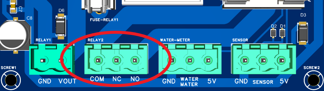
The RELAY2 connector on Autolejek provides COM, NC, and NO contacts.
Do not choose the contacts by guesswork. Consult the pump wiring diagram or test the kill switch with a multimeter. An incorrect connection may prevent automatic shutdown or stop the engine unexpectedly.
Example of starting the pump
Start using the pump switchSet the original pump switch to ON and start the engine. Then switch on Autolejek. Once its relay is energised, move the pump switch to OFF. The engine will continue running because the relay keeps the circuit open. Stopping Autolejek closes the circuit and stops the engine.
Start using the startup delayYou can switch on Autolejek first while leaving the pump switch in the OFF position. The energised relay opens the kill-switch circuit, allowing the engine to start. Configure a suitable startup period in Autolejek so minimum-flow monitoring begins only after the engine has started and the flow has stabilised.
Other engine-stopping methods
The method described above applies to a simple kill-switch circuit. Depending on its design, an engine may instead be stopped by:
a fuel shut-off solenoid,
an electronic STOP input on an engine controller,
a switch that stops the engine by opening rather than closing a circuit.
Example
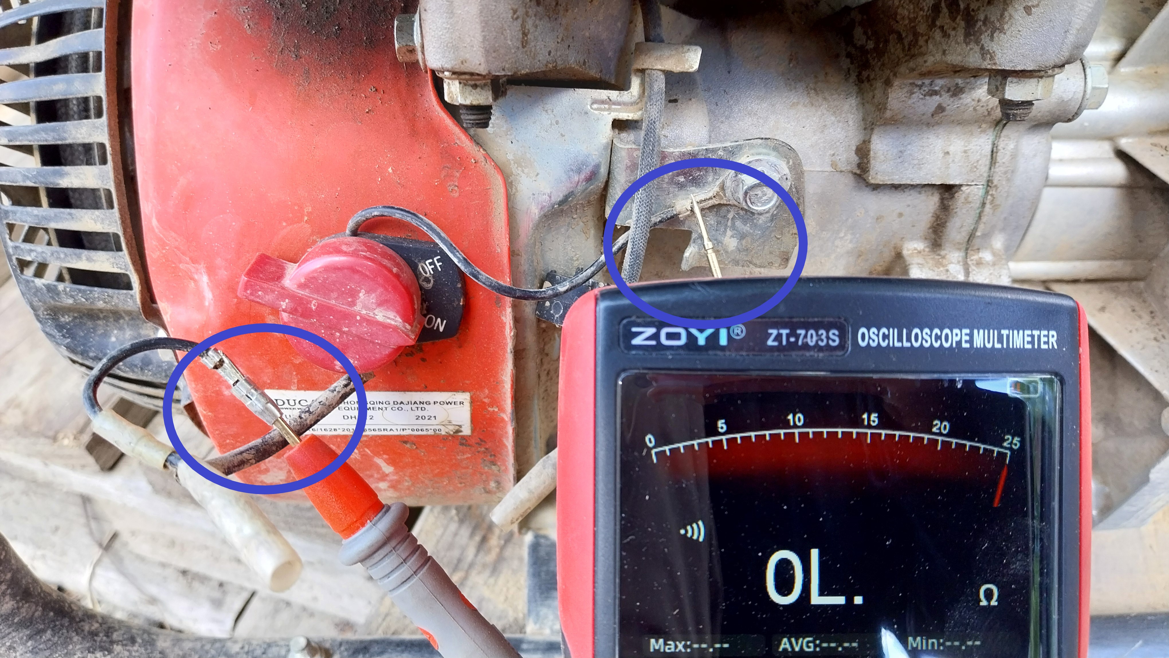
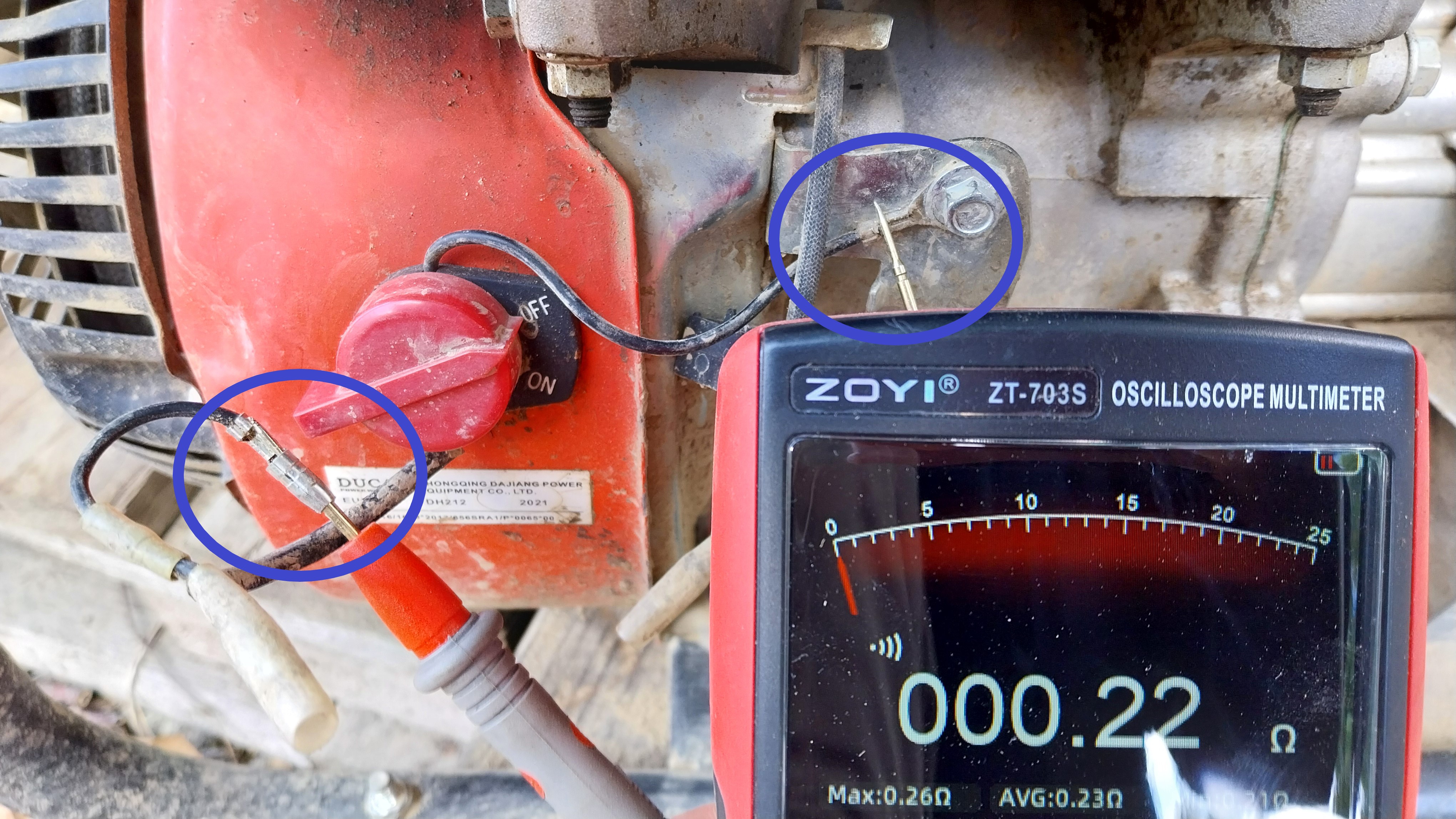
The measurement below shows how to determine whether a kill switch stops the engine by closing or opening its circuit. With the engine switched off and secured against accidental starting, set the multimeter to continuity mode (the diode or buzzer symbol) and test both the ON and OFF positions.
ON position: the multimeter displays OL, meaning no continuity. The kill-switch circuit is open and the engine can run.OFF position: the multimeter displays approximately 0.22 Ω, confirming continuity. The kill switch connects the wire to ground and stops the engine.
On this pump, the engine is stopped by connecting the kill-switch wire to ground. Other models may work in the opposite way, so always test both switch positions before connecting Autolejek.
7
Liquid level detector
One of Autolejek's features is support for a liquid level detector. A signal from the sensor can stop the entire process, protecting the installation from operating in unsafe conditions.
Dry-running protection
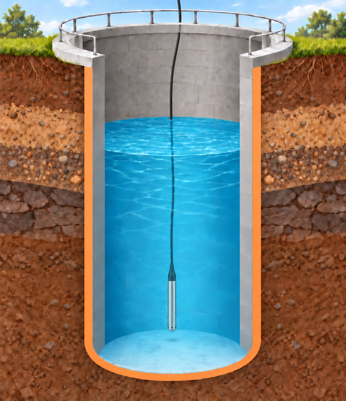
Consider a water tank with a pump inside it. A sensor installed near the bottom allows Autolejek to switch the pump off when the water level becomes too low. This prevents dry running and helps protect the pump from damage.
AI-generated illustrationA sensor near the bottom of the tank detects a low water level so Autolejek can stop the pump.
Overflow protection
The sensor can also be installed near the top of the tank. When the maximum level is reached, Autolejek stops the process and prevents the water from overflowing.
Power supply and signal logic
5 VThe sensor should use a 5 V supply and provide Autolejek with a digital high or low state. In the configuration, the user selects which signal state should stop the system. This setting must match the operation and wiring of the particular sensor.
Sensor types
Liquid levels can be detected in several ways. Sensors differ in operating principle, mounting method, and signal type. The right choice depends on factors including the liquid, tank material, available space, and required accuracy.
Float sensors
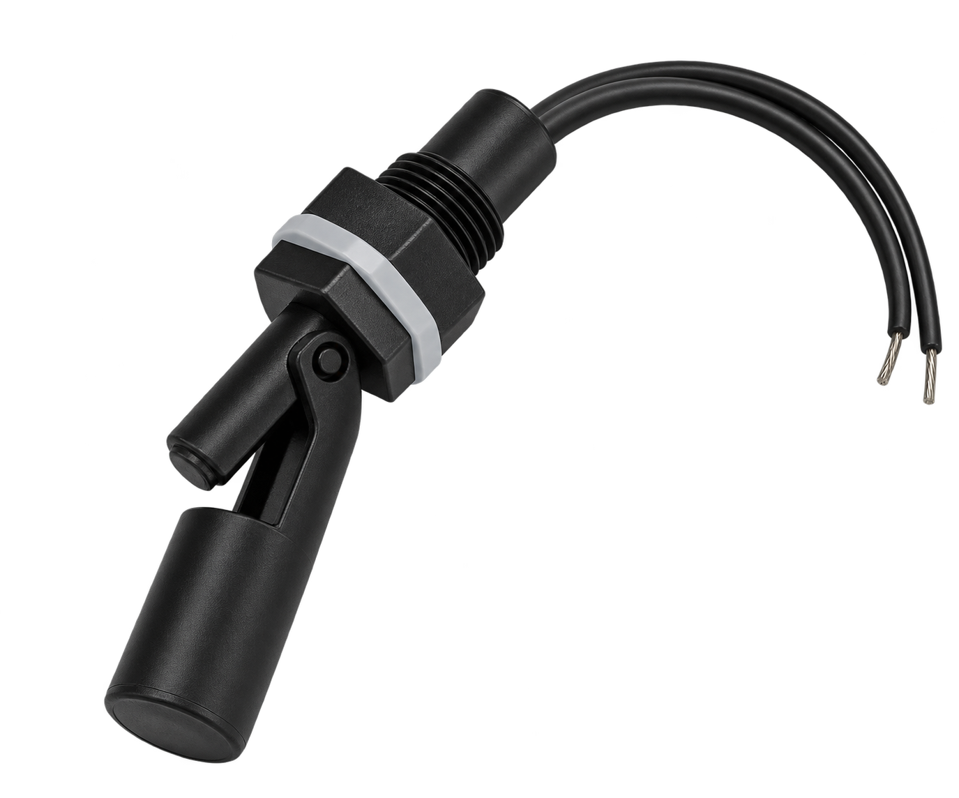
A float sensor is installed inside the tank at the selected height. A change in liquid level moves a magnetic float, which opens or closes a reed contact. This type is simple and needs no separate power supply, but it contacts the liquid directly. Its materials, seals, operating temperature, and mounting method must suit the specific installation.
AI-generated illustrationExample of a passive float-type liquid-level sensor.
Non-contact sensors
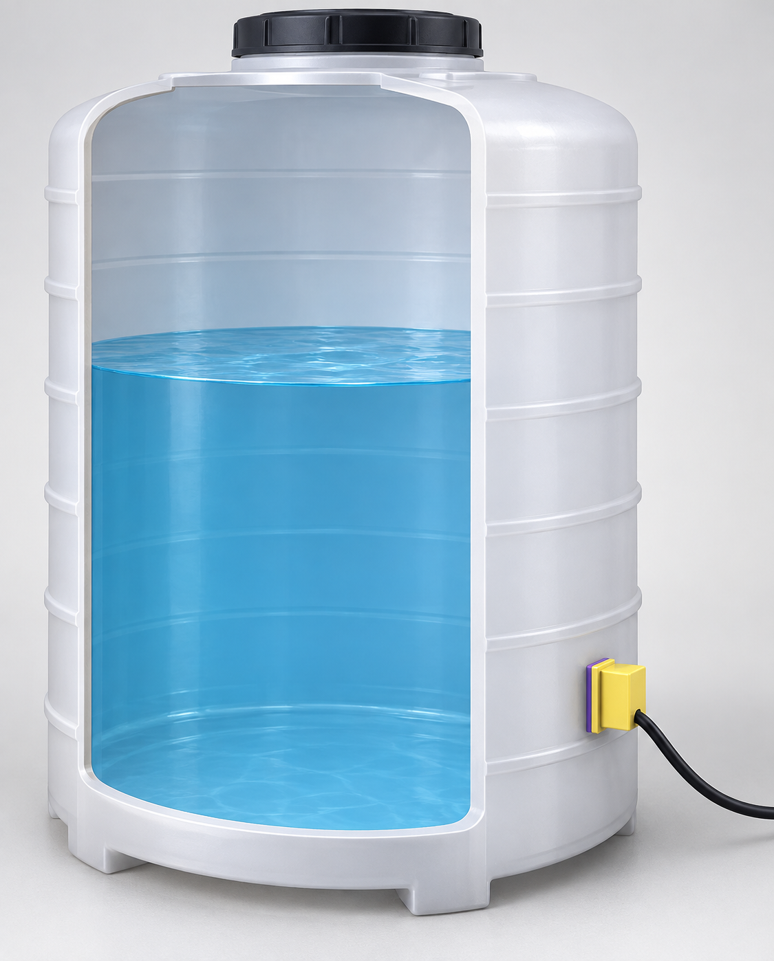
Non-contact sensors detect the level without immersing a measuring element in the liquid. The example shown is a capacitive sensor installed on the outside of a tank. It detects a change in electrical properties when liquid appears behind the wall. Performance depends on the liquid and on the tank material and wall thickness; this type usually does not work through a metal wall. Ultrasonic sensors form another group and are commonly installed above the liquid surface to measure distance from a reflected signal.
AI-generated illustrationExample of non-contact liquid-level monitoring through a tank wall.
Before purchasing a sensor, check its supply voltage, output type, active-state logic, and compatibility with the liquid and tank.
This section brings the previously selected components together. Start by tracing the water path: identify the source, pump or control valve, meter and outlet. Then consider what happens to water and air during filling, dosing and stopping.
Plan the component order
For a system with a pump and a dosing valve, a starting layout is: source → pump → inlet pipe section → meter → outlet pipe section → dosing valve → destination. With mains water, omit the pump; when dosing is controlled by the pump alone, a dosing valve may be unnecessary. This is a conceptual layout; select filters, check valves and service fittings for the actual equipment.
Always determine pipe section lengths and dimensions from the documentation for the water meter, solenoid valves and all other devices in the system. Check the required straight sections upstream and downstream of each device and the permitted mounting orientations. Account for these requirements around elbows, filters and valves too. The illustrations below are conceptual and do not specify installation distances.
U and D markings — pipe sections before and after the meter
U stands for upstream: the inlet side before the meter. D stands for downstream: the outlet side after the meter. Follow the water flow and the arrow on the body to identify these sides, rather than the device’s position in a photograph.
The numbers specify the required straight pipe lengths as multiples of the nominal diameter DN. For example, U5-D3 means at least 5 × DN upstream and 3 × DN downstream. For DN20, these lengths are 100 mm and 60 mm respectively. This is a calculation example, not the marking on the pictured meter.
The highlighted marking on this B METERS GSD8-R water meter is U0-D0.
U0-D0 means this meter class requires no additional straight pipe length upstream or downstream. Other installation requirements and the spacing specified for the pump, solenoid valve and other devices still apply. Always check the markings on your particular meter and the system documentation.
In this layout, install the flow meter downstream of the pump, on its discharge side, rather than upstream on the suction side. The pump then supplies pressurised liquid to the measuring section. Negative pressure on the suction side can expand air pockets. Air and an incompletely filled meter can cause incorrect or unstable readings.
Downstream placement alone does not guarantee a full pipe: also provide suitable pipe routing and air removal. Follow the pump and meter documentation for straight pipe lengths and permissible pressure. The B METERS MAG manual also warns that vacuum conditions can damage the electromagnetic meter lining and displace its electrodes.
Keep the pipe completely filled with water
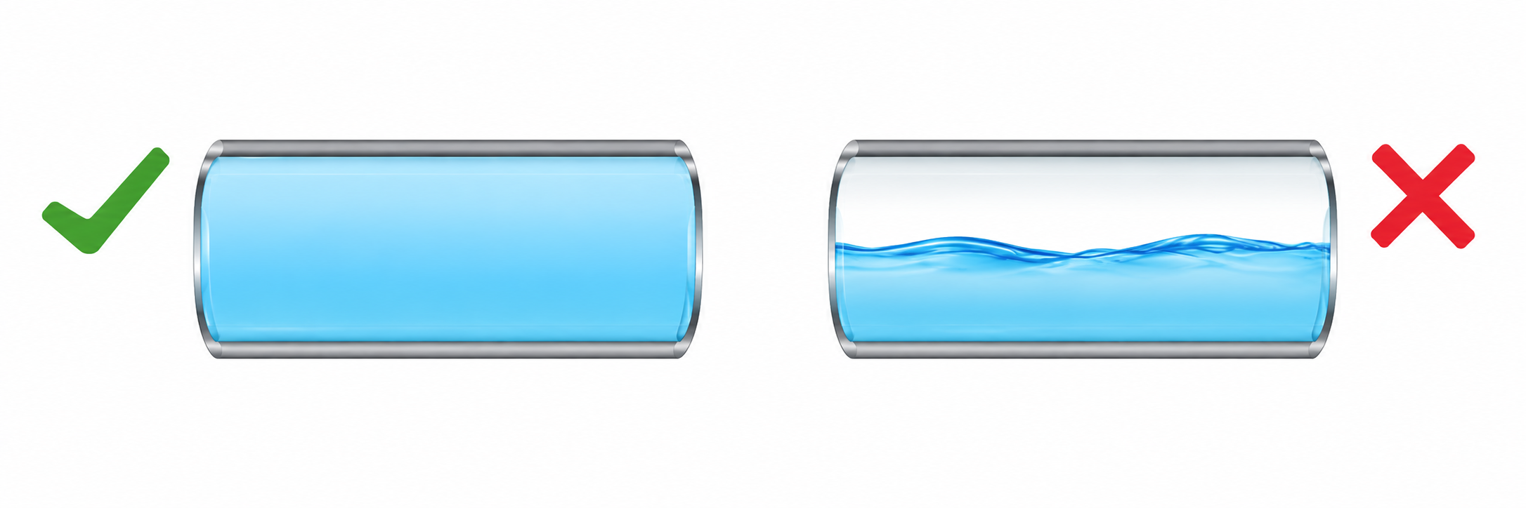
During measurement, the water meter and the pipe section containing it should be completely filled with water. Arrange the installation so that no air pocket remains at the measurement point.
AI-generated illustrationCorrect: water fills the entire pipe cross-section. Incorrect: an air gap remains above the water.
Vertical installation — upward flow
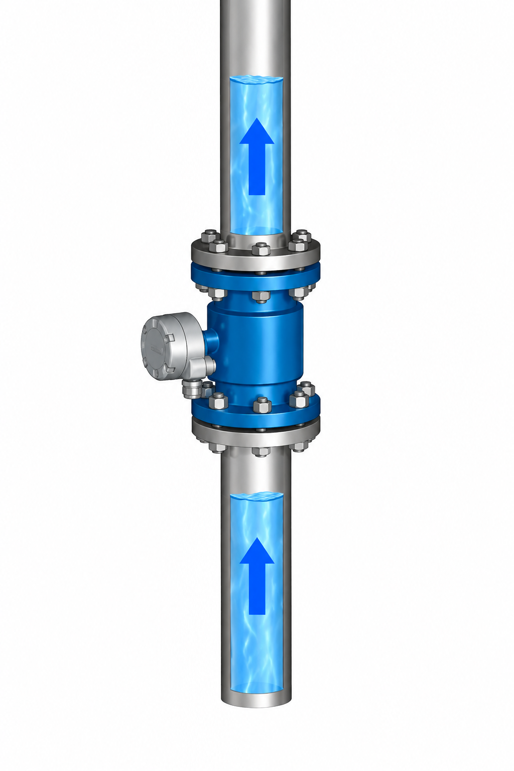
If the selected meter’s documentation permits vertical mounting, arrange upward flow in the Autolejek installation, following the arrow on the meter body. This direction helps keep the measuring section full and move air upwards rather than allowing it to collect at the meter. Provide a way to vent the system.
AI-generated illustrationVertically mounted flow meter with upward flow: inlet below and outlet above. The blue sections illustrate flow direction; the measuring pipe must be completely filled with water during measurement.
In this orientation, U (upstream) is below the meter and D (downstream) is above it. Observe the required straight pipe lengths, permissible pressure and measurement specifications for vertical mounting, which may differ from horizontal mounting. Avoid a descending section with a free outlet that can leave the meter partially empty.
Where should the meter go?
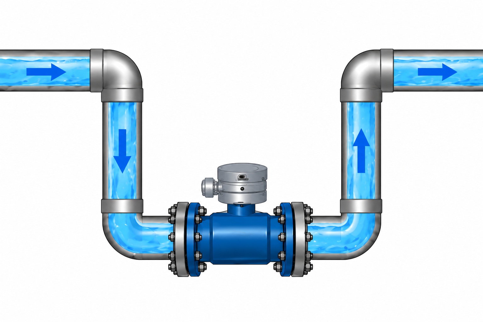
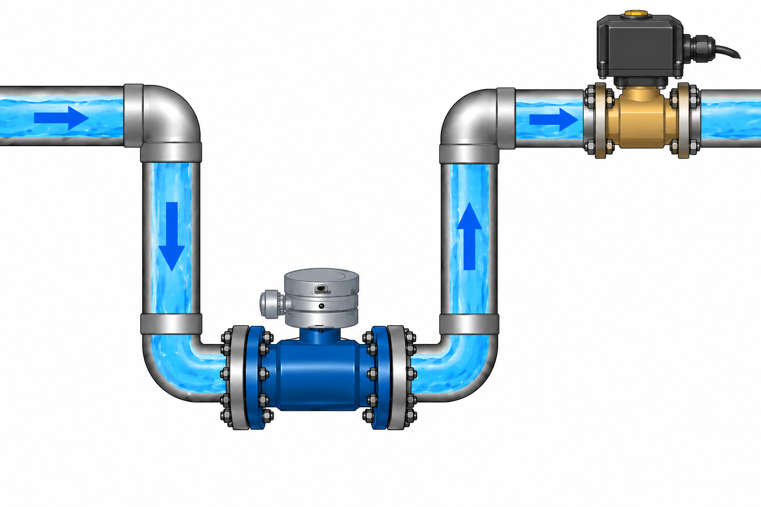
Correct: a lowered measuring section
AI-generated illustrationThe meter sits at the bottom of a U-shaped section. The downstream pipe rises again, helping retain water. This illustrates the principle; determine straight pipe lengths separately.
Incorrect: the highest point of the pipe
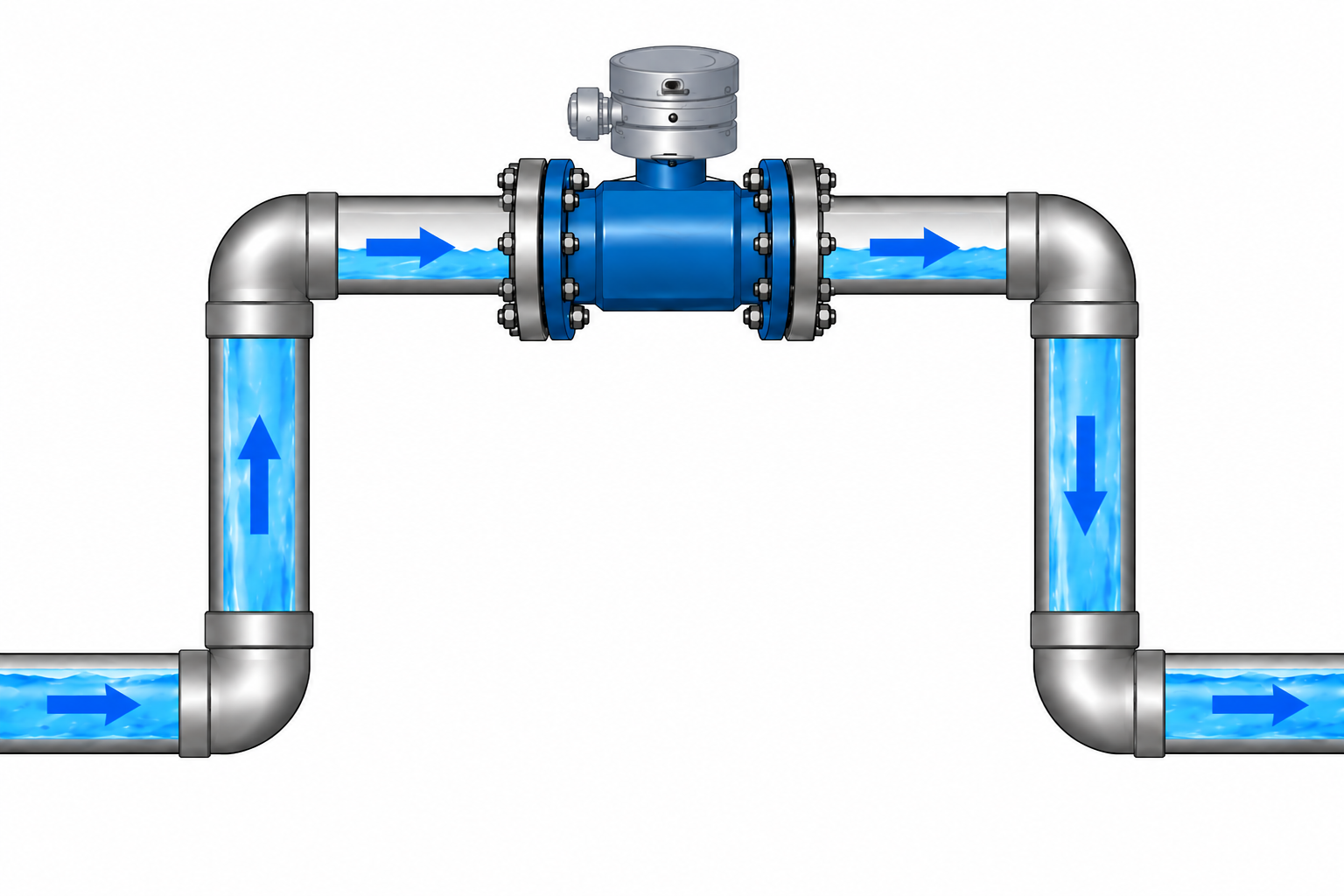
AI-generated illustrationAir can collect in the upper section. Flowing water does not mean the meter cross-section is completely filled.
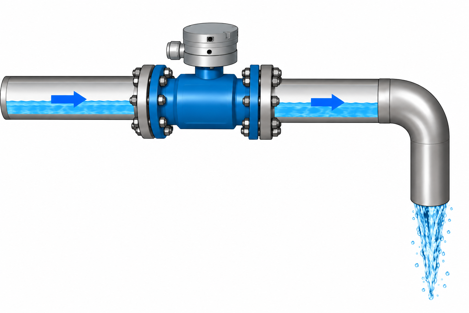
Incorrect: a descending pipe with a free outlet
AI-generated illustrationAn open outlet below the meter allows the measuring section to drain. Flow in this layout does not ensure a full pipe.
Solenoid valve downstream of the flow meter
The solenoid valve is usually installed downstream of the flow meter, in the direction of water flow. Maintain the distances and mounting orientations required by the documentation for both devices.
AI-generated illustrationExample layout: the flow meter sits in a lowered pipe section, followed by the solenoid valve in the direction of flow. Determine pipe section lengths from the equipment documentation.
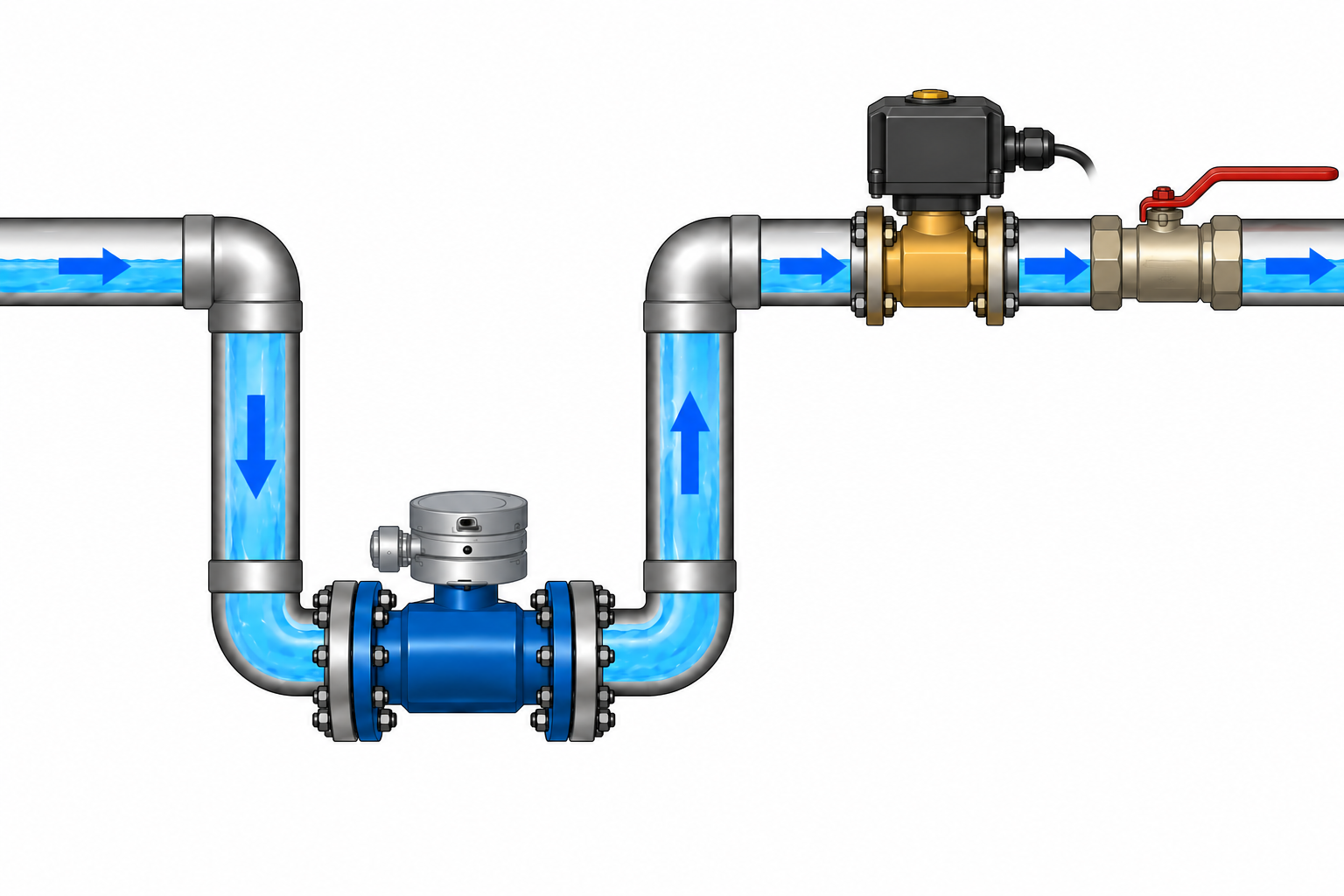
A simple way to reduce excessive flow
If the flow rate is too high, you can add a manual valve and partially close it to reduce the amount of water passing through per unit of time. This is an inexpensive, practical way to match the flow to your installation. In the illustrated layout, the manual valve is downstream of both the flow meter and the solenoid valve: you set the flow manually, while the solenoid valve still starts and stops dosing automatically.
AI-generated illustrationExample order: flow meter → solenoid valve → manual valve for reducing flow. The illustration shows component placement, not the required spacing or the handle position for regulation.
Choose a valve approved by its manufacturer for flow regulation while partially open. Adjust it gradually while monitoring flow and staying within the operating ranges of the pump, flow meter and solenoid valve. Check their documentation for the required spacing between components.
Assembly and first startup
Before assembly, check component flow arrows, connection compatibility and access for disconnection and cleaning. Leave room to remove the meter without dismantling the entire installation.
Support and align the pipes without stress. The meter must not carry the pipework; do not pull misaligned pipes together using flange bolts.
Before the first dose, fill the installation and remove air. Check joints for leaks and confirm that water actually stops reaching the destination when the pump stops or the valve closes.
Connect the pulse output according to the selected meter manual and set the pulse conversion in Autolejek. Test against a measured volume and check how the system behaves after restarting.
The B METERS MAG manual recommends placing the meter downstream of the pump and valves downstream of the meter. It covers electromagnetic meters: always check grounding, connections, straight pipe lengths and electrical outputs for your own model.B METERS MAG — manual, chapters 4–6 (PDF, EN)
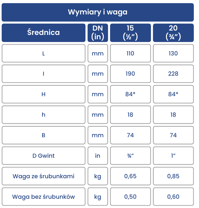 Illustration from manufacturer documentation