Here you will find the information needed to start and correctly configure Autolejek for your own installation.
1
Power supply and mounting location
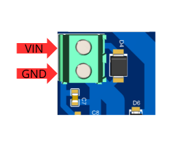
VIN supplies power to the controller. Disconnect power before wiring and measure the unloaded supply voltage; it must not exceed 32 V DC. Check polarity and cable condition.
Power connection: positive supply wire to VIN, negative wire to GND.
Secure the wires so they cannot touch adjacent terminals. Switch on only after checking the connections. Do not connect a supply if wires are loose or insulation is damaged.
Controller mounting conditions
Mounting dimensions: 140 × 80 mm; corner radius: 3 mm. Choose a dry, sheltered location with access to the keypad, display, switch and cables. Do not install or store the controller in damp conditions, rain, heavy dust, direct sunlight or temperatures below 0°C or above 40°C.
2
Connecting a flow meter or water meter
How do you connect a water meter to Autolejek?
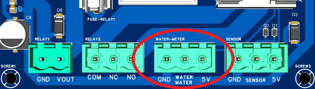
The Autolejek water-meter or flow-meter connector has three terminals: 5V, SIG, and GND. How they are used depends on the device's pulse-output type.
The water-meter connector on the Autolejek circuit board.
WATER MATER = SIGThe middle pin, labelled WATER MATER on the circuit board, is the SIG input for the water meter or flow meter.
≤ 200 mAA water meter or flow meter powered from the 5V terminal must not draw more than 200 mA. This is the maximum current available from the connector's power output, not the pulse-signal current.
Flow-meter input terminals
Terminal
Function
What to connect
5V
+5 V supply
Sensor supply wire, only if the device requires and supports 5 V
SIG
Pulse input
Water-meter pulse-output wire
GND
Circuit ground
Sensor ground wire or the second wire of a volt-free contact
Water meter with a passive reed switch
If the transmitter is an ordinary volt-free reed switch, connect one wire to SIG and the other to GND. Leave the 5V terminal unconnected. The Autolejek SIG input has its own 2.2 kΩ pull-up to 5 V, and closing the reed switch to GND creates the transition counted as a pulse.
SIG ↔ GNDConnect a passive contact between SIG and GND. Do not apply an additional voltage to the contact.
Example — B METERS pulse emitter
This type of passive reed-switch pulse emitter is used, among others, in the B METERS GSD8-R water meter.
Brown → GNDConnect the brown wire to the GND pin.
Blue → SIGConnect the blue wire to the middle WATER MATER pin, which is SIG.
5V → do not connectA passive reed switch does not need a separate supply wire, so leave the 5V pin unused.
The manual gives this colour convention for the basic GSD and GMDX sensors. Electrically, swapping the brown and blue wires does not affect operation because this is an ordinary reed contact with no polarity. The manufacturer also notes that wire colours may change without notice, so check the documentation supplied with the particular unit.
For a typical three-wire sensor, connect its supply wire to 5V, ground to GND, and pulse output to SIG. Before wiring, verify that the sensor supports a 5 V supply, its output is compatible with 5 V logic, and its current consumption does not exceed 200 mA. An open-collector output requires the sensor ground and Autolejek GND to be common.
Example — SEA YF-G1
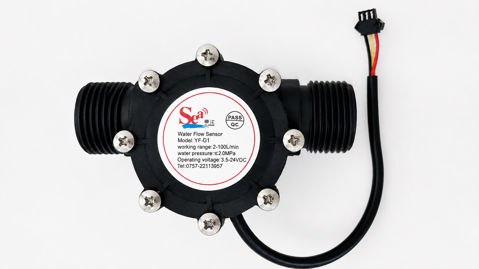
The SEA YF-G1 is an active three-wire flow sensor based on a Hall-effect sensor. Unlike a passive reed switch, it requires a power supply. The documentation for this variant permits a 5 V supply and specifies a current draw of up to 15 mA at that voltage, so it can be powered directly from the Autolejek water-meter connector.
SEA YF-G1 — an active three-wire water-flow sensor.
Red → 5VConnect the red supply wire to the 5V pin.
Black → GNDConnect the black ground wire to the GND pin.
Yellow → SIGConnect the yellow pulse-output wire to the middle WATER MATER pin, which is SIG.
Connect the wires only while power is switched off. Check the markings supplied with the particular unit before wiring it—different variants are sold under the YF-G1 name, and wire colour alone should not be used for identification.
The voltage on SIG must not exceed 5 V. Never connect a 12 V or 24 V signal directly to this input. If the water-meter output is not compatible with a 5 V input, use a suitable interface circuit instead of connecting the devices directly.
3
Connecting a solenoid valve or another device
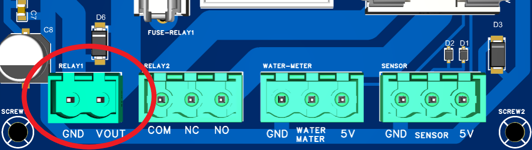
As explained in the “Build it yourself” section, Autolejek is designed so that when the system is running and relay no. 1 is selected as active, the RELAY1 connector supplies the same voltage as the controller input. This is useful when selecting a solenoid valve or another device whose switching voltage matches the system supply voltage.
RELAY1 supplies the Autolejek input voltage when relay no. 1 is energised.
URELAY1 = UINWhen RELAY1 is energised, its connector supplies the same voltage as the Autolejek power input.
Example — HPControl 2N25 solenoid valve
This example uses an HPControl 2N25 solenoid valve with a 12 V DC coil. Wire it according to the manufacturer's documentation:2N-series solenoid valve manual (PDF).
Wiring a 12 V DC coil
Coil terminal
Connection to Autolejek
1
VOUT
2
GND
VOUTRelay no. 1 switches the VOUT line, not GND. The GND terminal remains a permanent connection to the system ground.
Connect wires only while power is switched off. Check the terminal markings on the specific coil before startup. Correct polarity is especially important when the coil or plug contains a diode or another protection circuit.
4
Connecting a detector
How do you connect a detector to Autolejek?
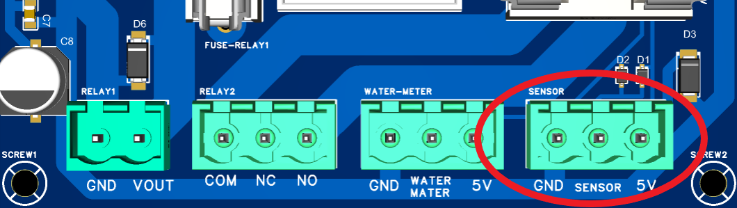
The Autolejek detector connector has three terminals: 5V, SENSOR, and GND. Their use depends on the output type of the sensor.
The SENSOR detector connector on the Autolejek board.
SENSOR = SIGThe middle pin, labelled SENSOR on the board, is the detector signal input.
≤ 200 mAA detector powered from the 5V terminal must not draw more than 200 mA. This is the maximum current available from the connector's power output, not the signal current.
Detector input terminals
Terminal
Function
What to connect
5V
+5 V supply
Sensor supply wire, only when the device requires and supports 5 V
SENSOR
Signal input
Detector signal-output wire
GND
System ground
Sensor ground wire or the second wire of a volt-free contact
Detector with a passive contact
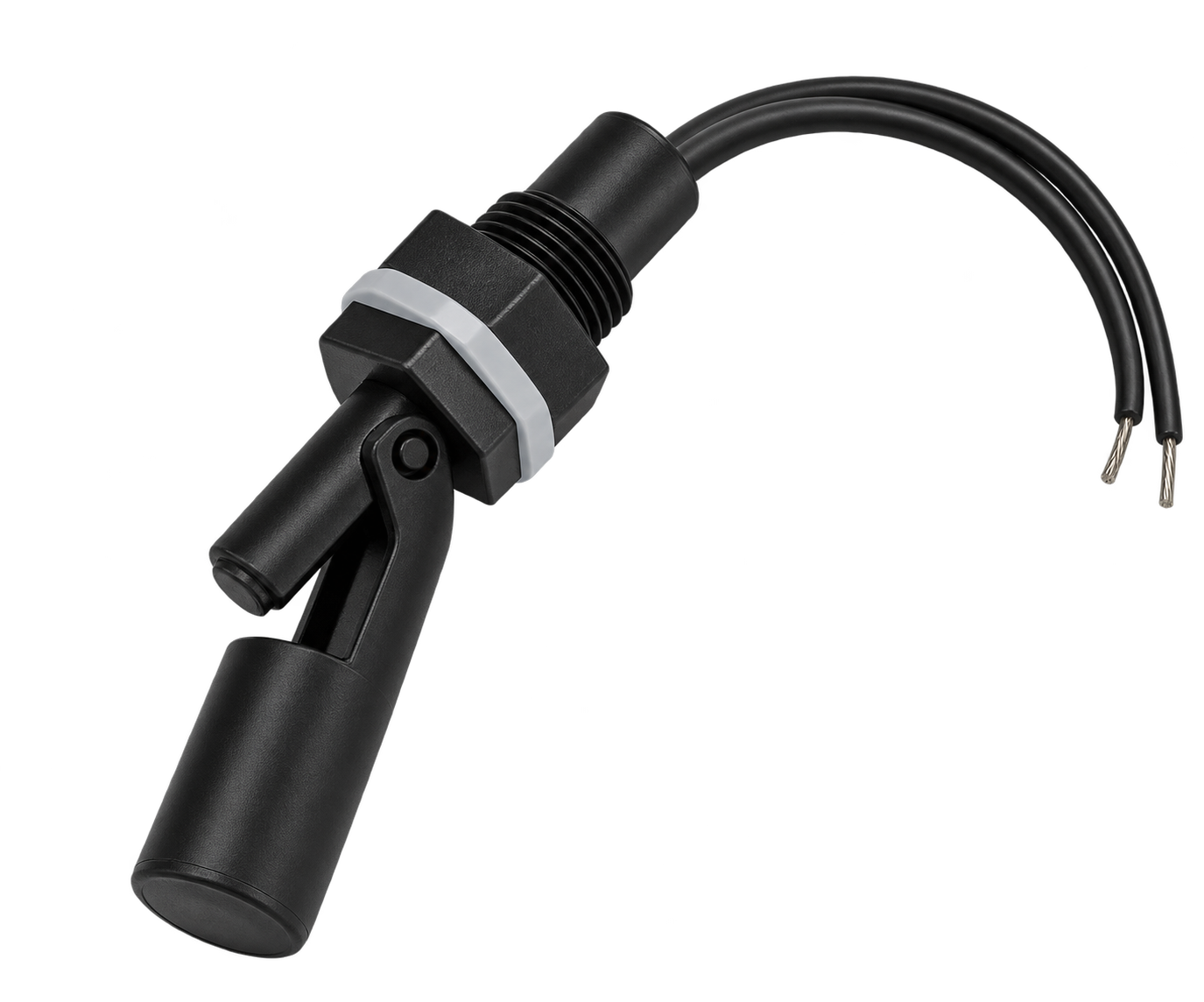
If the detector is an ordinary volt-free contact, such as a float switch or limit switch, connect one wire to SENSOR and the other to GND. Leave the 5V terminal unconnected. The SENSOR input has its own 2.2 kΩ pull-up resistor to 5 V inside Autolejek, and closing the contact to GND changes the input state.
AI-generated illustrationExample of a passive float-type liquid-level sensor.
Every level detector must be suitable for the liquid being detected, the tank material, and the installation's operating conditions. Not every sensor can be used with drinking water, fuel, oil, fertiliser, corrosive substances, or high-temperature liquids. Before installation, confirm with the manufacturer that the sensor, cable, and seal materials, measurement method, and mounting arrangement are compatible with the liquid, its temperature and pressure, and the tank wall.
SENSOR ↔ GNDConnect a passive contact between SENSOR and GND. Do not apply an external voltage to such a contact.
Example — CMW115 magnetic float sensor
The CMW115 is a passive magnetic float sensor with a reed contact. Movement of the float as the liquid level changes opens or closes the contact. The sensor is 118 mm long and 17 mm in diameter, with a cable approximately 0.5 m long. The seller states maximum contact ratings of 0.1 A and 50 V DC; the Autolejek input places a much smaller load on it.
SENSORConnect either of the sensor's two wires to the SENSOR input.
GNDConnect the other sensor wire to GND. The reed contact has no polarity, so swapping these two wires does not affect operation.
5VLeave this terminal unconnected—the passive reed contact does not require a separate power supply.
For a typical three-wire sensor, connect its supply wire to 5V, ground to GND, and signal output to SENSOR. Before wiring, verify in the documentation that the sensor supports a 5 V supply, its output is compatible with 5 V logic, and its current consumption does not exceed 200 mA. An open-collector output requires the sensor ground and Autolejek GND to be common.
Example — DFRobot SEN0204
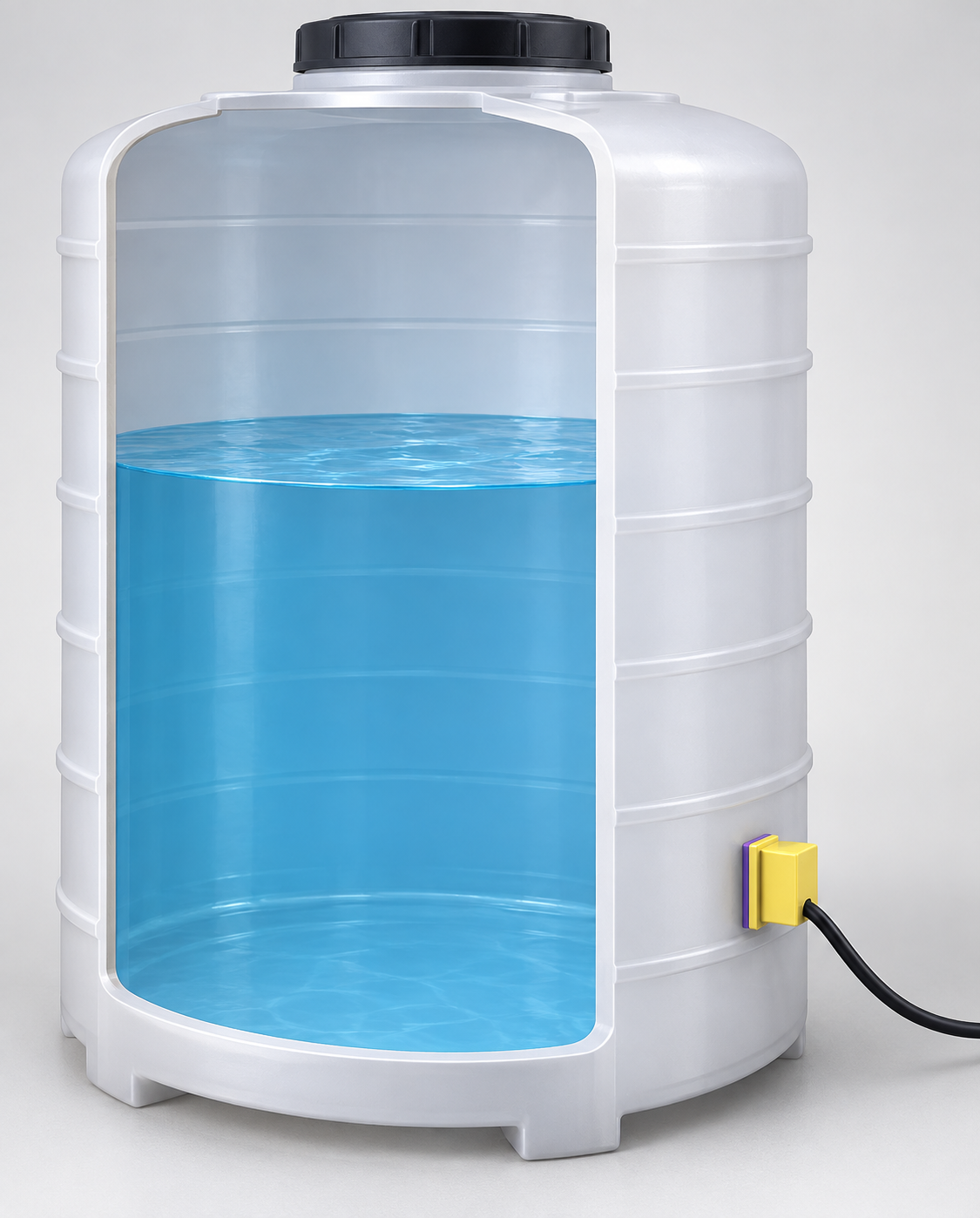
The DFRobot SEN0204 is a digital non-contact liquid level sensor. It can be installed on the outside of a suitable tank, so it does not contact the liquid. The manufacturer specifies a 5–24 V supply, 5 mA current consumption, a 500 ms response time, and detection through a tank wall up to 13 mm thick.
AI-generated illustrationExample of non-contact liquid-level monitoring through a tank wall.
VCC → 5VConnect the sensor supply wire to the Autolejek 5V terminal.
OUT → SENSORConnect the sensor's digital signal output to the middle SENSOR terminal.
GND → GNDConnect the sensor ground to the Autolejek GND terminal.
5 VWhen using this sensor with Autolejek, power it only with 5 V. According to the manufacturer, the OUT high-state voltage equals the supply voltage. Powering the sensor with 12 V or 24 V would apply the same voltage to the SENSOR input and could damage the controller.
Signal logic and alarm setting
When the SEN0204 detects liquid, its OUT pin changes to the high state—approximately 5 V with the recommended Autolejek connection. When the sensor no longer detects liquid, its output changes to the low state, approximately 0 V.
Low-level protection — falling signalWhen the sensor is installed near the bottom of the tank, loss of liquid changes the signal from 5 V to 0 V. Set the Autolejek detector signal mode to falling. The alarm activates when the sensor stops detecting liquid.
High-level protection — rising signalWhen the sensor is installed near the top of the tank, liquid reaching the sensor changes the signal from 0 V to 5 V. Set the Autolejek detector signal mode to rising. The alarm activates when liquid is detected at this height.
The voltage at the SENSOR input must not exceed 5 V. Do not connect a 12 V or 24 V signal to it. After wiring, configure the detector's active state and verify its operation in a controlled test.
5
Recommended initial configuration procedure
During initial startup, configure at least the calibration, flow meter, maximum tank capacity, and active relay. Without these parameters, the controller cannot count liquid correctly, enforce the permitted filling limit, or activate the correct output. Observe the actual liquid flow during a test fill and use it to select the minimum-flow limit. For example, if normal flow is approximately 23 L/min, the minimum flow can be set to 15 L/min.
Before filling, prepare a quick stopping method: A or B on the filling screen and disconnecting power to the actuator circuit. Alarms and the detector do not replace operator supervision.
Before switching on the power, compare the equipment, connections, protection and cables with the installation wiring diagram. Define the supply voltage and capacity, cable types, lengths and routing, and required shielding and ground/PE connections. Record these details in the project documentation.
Set the interface language in Settings > Language as described in section 6.1, Language.
Set flow-meter calibration in Settings > Calibration as described in section 6.2, Calibration.
Set the maximum tank capacity in Settings > Liquid limit as described in section 6.3, Liquid limit.
Check the flow-meter signal mode as described in section 6.4.1, Signal edge.
Select the active relay or both relays as described in section 6.5, Relays.
If you use an additional sensor, enable and configure the Detector as described in section 6.6, Detector.
Observe the current liquid flow during a test fill. Then configure the minimum-flow alarm in the Flow menu as described in section 6.7.1, Minimum flow, selecting a limit below the normal flow.
To protect the flow meter against excessive flow, enable the maximum-flow alarm in the Flow menu as described in section 6.7.2, Maximum flow, and set its limit.
Return to the main screen, enter a small test limit, and perform a test.
During a controlled trial, check counting, the detector and relays while starting the pump and switching the valve. Check that no pulses are counted without flow and verify behaviour after switching the power off and back on.
Record equipment models, hardware and firmware versions, settings and trial results. Resolve false pulses, resets or unintended switching before normal operation; increasing the filter time alone does not complete the diagnosis.
Discuss changes to the power supply, cables, enclosure, pump, valves and firmware with the person responsible for the installation. Update the documentation and determine which checks must be repeated.
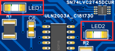
LED1 corresponds to relay P1 and LED2 to relay P2. An illuminated indicator means that relay is energized.
LED3 indicates failed communication with the display during the startup test; LED4 indicates failed communication with the keypad controller. If an indicator stays on after startup, disconnect power and check the relevant module connection. These indicators do not monitor communication during normal operation.
A replacement fuse blows again
Disconnect power to the controller and switched circuit. Check the load, cables, insulation and terminals. Do not fit a fuse with a higher current rating. Replace it after resolving the cause; if the cause is unclear, have a qualified person diagnose the installation.
The volume increases without flow
Do not start normal filling. Check the GND connection and signal cable routing relative to pump and relay wiring. Set filtering according to the sensor documentation and check whether the cable needs shortening or shielding.